Injection Mold Manufacturing: Where Part Quality Is Decided
A plastic part is only as good as the tool that makes it. Tolerances the molding process must hold are established by the steel cavity; the surface finish the customer sees is cut by the polisher; cycle time is set by the cooling layout. Mold manufacturing is therefore not a precursor to production — it is the foundation of it. Choosing the right mold maker is as strategic as choosing the molder, and keeping both under one roof removes the hand-off risk that erodes quality between them.
This page focuses on the tooling itself: how molds are designed and built, how steel and runner choices affect the life and cost of your program, and what to verify before a tool cuts its first production part.
The Mold Types We Build
Production tooling spans the full spectrum of injection mold architectures:
- Multi-cavity production molds for high-volume components, where balanced filling protects consistency.
- Insert molds for metal-plastic combinations in a single cycle.
- Overmolds bonding TPE to a rigid substrate for soft-touch and sealing features.
- High-gloss optical molds with mirror-polished cavities for lenses and covers.
- Stack molds that double output per cycle for qualified geometries.
Tooling lead time runs 15 to 35 days depending on complexity, and production molds are guaranteed for 300,000 to 1,000,000 shots based on steel and resin selection. Aluminum prototype tooling is also built for bridge and validation programs where speed matters more than ultimate life.
Mold Design and Engineering
Every mold starts with a design review covering parting line, gating, cooling layout, ejection, and slider or lifter requirements. Fill and cooling are simulated where needed to predict warpage and balance cavity pressures before machining begins — because correcting a cooling imbalance after steel is cut is exponentially more expensive than designing it out.
Good cooling design is the difference between a fast, stable cycle and a tool that fights itself. Balanced and conformal cooling keeps cycle times short and dimensions consistent across the run. Gate location and size are chosen to minimize weld lines and stress, and ejection is designed to avoid marks on visible surfaces. These are the details a buyer cannot see in a quote but lives with in every shipment.
Selecting the Right Tool Steel
Steel selection drives mold life, surface quality, and cost. The choice should follow the program, not a default:
| Steel | Best for |
|---|---|
| P20 | Pre-hardened, cost-effective for moderate runs |
| 718H | Improved hardness and polishability for longer life |
| NAK80 | Mirror polish for optical and high-gloss parts |
| S136 | Stainless, for corrosive or medical resins |
| Aluminum | Prototype and bridge tooling where speed leads |
The right steel is the cheapest choice over the life of the program, not the cheapest choice on the purchase order. Specifying S136 for a medical resin that would corrode a standard steel avoids a failure no inspection can catch after the fact.
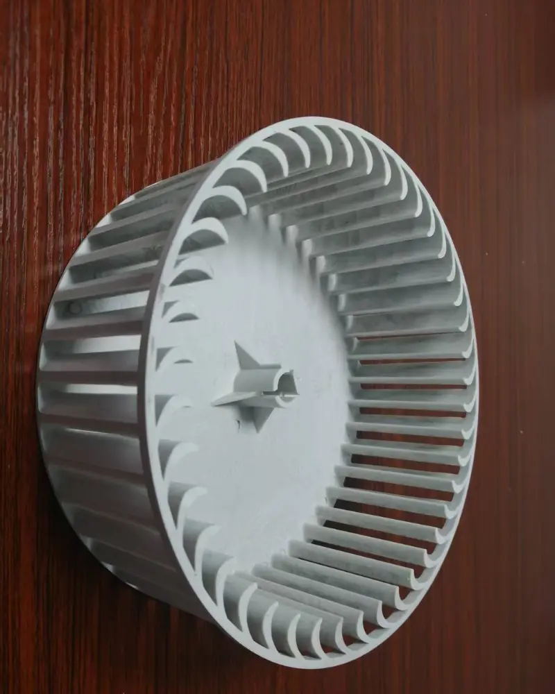
Components molded from in-house fabricated precision injection molds, where cavity quality sets the part tolerance.
Hot-Runner and Runner Systems
Hot-runner molds eliminate cold sprue waste, shorten cycle times, and improve part consistency for high-volume programs. The manifold is sized to the resin and cavity count, with balanced flow so every cavity fills identically. For lower-volume or frequent color-change programs, a well-designed cold-runner tool keeps cost down while maintaining quality. The runner decision is a trade-off between material savings, cycle time, and tool cost — one our engineers help you make deliberately rather than by default.
Why In-House Tooling Protects Your Program
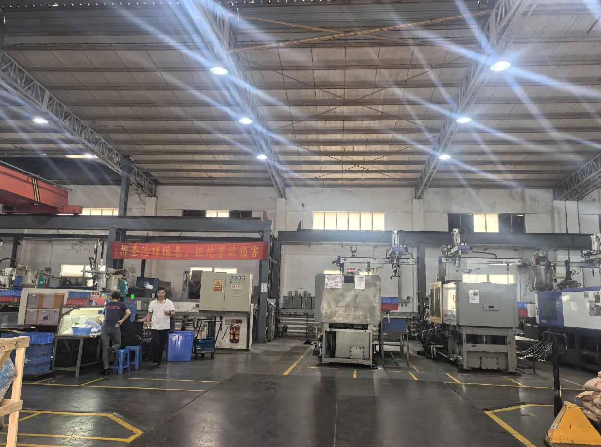
When tooling and molding share a building, three things improve at once. Change loops shrink, because a mold modification does not wait on a separate shop’s queue. Accountability is single-sourced, because one team owns both tool and part quality. And the tool is tuned to the press it actually runs on, not to a generic spec. For the customer, these translate into shorter lead times, fewer interface problems, and a tool that performs as designed from the first article.
Quality Verification Before First Production Part
Mold quality is verified before the first production part is molded. Cavities are inspected with CMM, the tool is validated on a tryout press, and steel certifications and heat treatment are documented. Maintenance is scheduled by shot count so wear is managed rather than discovered, and spare wear components are planned so a planned stop never becomes an unplanned one. The result is a tool whose behavior is known, not assumed.
Industries and How They Stress the Tool
Each sector weights tool design differently. Automotive demands life and PPAP documentation; medical demands cleanliness, documentation, and corrosion-resistant steel; electronics demands fine features and tight cavities; industrial demands robustness under load. The design process accounts for those factors from the first review rather than bolting them on later.
Mold Life and Total Cost of Ownership
A mold is a capital asset whose cost is amortized across its shots. A tool built for 1,000,000 shots costs more upfront than one built for 300,000, but the per-part tooling cost falls as volume rises. The right decision depends on your forecast: over-specifying steel for a short run wastes money; under-specifying for a long run forces early re-tooling. Matching steel and cavitation to realistic volume is one of the highest-value conversations in a mold-making program.
What to Provide for a Tooling Quote
Send your 3D model and 2D drawing, target resin and any additives, expected annual volume and program life, critical dimensions with tolerances, surface finish requirements (SPI class or VDI grade), and any ejection or insert constraints. If the part is still in design, share the model early — mold design benefits as much from DFM as the molding process does.
Design Guidelines That Make the Tool Right
A mold is designed for the part it must produce, and the early decisions decide everything downstream. Parting lines should be placed where they will not show or leak; gates sized and located to balance fill and minimize weld lines; cooling laid out to be uniform rather than convenient. Ejection must clear visible faces, and sliders or lifters specified only where the geometry forces them. Simulating fill and cooling before machining predicts warpage and imbalance, so the tool is validated on the screen before it is cut in steel — the cheapest place to be wrong.
Tolerances, Inspection, and Tool Qualification
The mold, not the press, establishes the part tolerance, so cavity quality is verified before the first production shot. Cavities are inspected by CMM, the tool is validated on a tryout press, and steel certifications and heat treatment are documented. Maintenance is scheduled by shot count so wear is managed rather than discovered, and spare wear components are planned so a service stop is never unplanned. This qualification is what lets a tool hold its promise across hundreds of thousands of shots.
Selecting Steel and Runner for Life and Cost
Steel choice follows the program, not a default. P20 suits moderate runs; 718H and NAK80 extend life and polishability; S136 resists corrosion for medical and aggressive resins; aluminum serves prototype and bridge tooling where speed leads. Hot-runner systems cut sprue waste and cycle time for volume, while well-designed cold runners keep cost down for lower volumes or frequent color changes. The runner decision trades material savings, cycle time, and tool cost — a trade our engineers help you make deliberately.
Cost Structure of a Tooling Program
Tooling cost is amortized across its shots, so the right steel and cavitation depend on realistic volume. Over-specifying steel for a short run wastes money; under-specifying for a long run forces early re-tooling. The largest hidden cost is a tool that needs rework because DFM was skipped — a change that is cheap on the drawing and expensive in hardened steel. A transparent tooling quote itemizes steel, cavitation, and qualification separately from piece price.
Lead Times, Logistics, and Confidentiality
Tooling lead time runs 15 to 35 days depending on complexity, and in-house fabrication keeps that schedule controllable. Finished tools and the parts they produce are handled with lot traceability, and shipments to North America, Europe, and Asia carry the required documentation. Customer designs are treated as confidential; a tool built for one program is never reused or offered to another.
Evaluating a Mold-Making Partner
Ask whether tooling is built in-house, whether cavity quality is CMM-verified before production, and whether the same team also runs the molding so the tool is tuned to its actual press. A mold maker who also molds understands which design choices survive at volume — and that understanding is what protects your part long after the tool is paid for.
What a Typical Tooling Program Looks Like
A representative multi-cavity tool follows: design review and fill simulation in week one; steel procurement and machining in weeks two to five; tryout and CMM cavity validation in week six; pilot run and approval in week seven; then release to production molding. Complexity — sliders, lifters, hot runners — extends the schedule within the 15 to 35 day window. The discipline that matters is verifying the cavity before production, because a tool that passes CMM and tryout is a tool that will hold its tolerance for its rated life.
Industry-Specific Considerations
Automotive tools are built for life and PPAP evidence. Medical tools favor S136 and clean-room compatibility, with documentation for audits. Electronics tools demand fine cavities and tight tolerances for small features. Industrial tools prioritize robustness under load. The design process weights these factors from the first review rather than retrofitting them, which is why the same tool performs differently depending on who designed it.
Glossary of Key Terms
- Cavity — the shaped space in the mold that forms the part.
- Hot runner — a heated manifold delivering melt without a cold sprue.
- NAK80 / S136 — mirror-polish and stainless tool steels respectively.
- PPAP — production part approval process, the automotive quality standard.
- SPI finish — U.S. mold surface finish classification from A to D.
- Tryout — validating a new mold on a press before production release.
Common Defects and How They Are Prevented
Tool-related defects are designed out before steel is cut. Flash follows worn parting lines or insufficient clamp; sink marks trace to poor cooling layout; short shots come from unbalanced fill; drag marks result from insufficient draft. Simulating fill and cooling during design predicts these, and CMM verification of the cavity before production confirms the tool is correct. Scheduled shot-count maintenance then keeps the tool in tolerance rather than waiting for it to fail.
Reading and Comparing Tooling Quotes
A tooling quote should state the steel, cavitation, runner system, and qualification scope separately, and confirm whether tryout and first-article validation are included. Vague quotes that lump everything into one number hide the trade-offs between steel life and cost. The right comparison weighs total cost of ownership across the program’s shots, not just the upfront tool price.
Communication and Project Management
Mold making is iterative, and clear communication prevents costly waits. Tryout reports, cavity inspection data, and steel certifications should be shared on a defined schedule, and change requests turned around quickly because the same team owns tool and molding. That integration is what lets a tool be corrected in days rather than weeks when a design inevitably moves.
Getting Started With a Tooling Program
Starting a tooling program begins with the part drawing and the production intent behind it. Share the 3D model, target resin, volume, and surface finish, and the design review will address parting line, gating, cooling, and ejection before steel moves. Because tooling and molding share a floor, tryout and any correction happen quickly, and the tool you approve is the tool that actually runs.
Mold Maintenance and Ownership
A tool is an asset the supplier should help you own confidently. Maintenance is scheduled by shot count, wear components are planned, and records are retained so you know the tool’s status at any time. When the program ends, the tool can be returned or stored under agreement — you retain control of the asset your production depends on, with the documentation to prove its history.
Decision Guide
When to invest in a tooling program. You need a mold built, rebuilt, or transferred when you own the part, when volumes justify dedicated tooling, or when an existing tool has reached end of life. Building in-house or with a dedicated toolmaker also matters when lead time and revision control are critical.
Factors that shape the decision. Target mold life, required cavitation, hot versus cold runner, steel grade, and the surface finish class. Who services the tool and where it is stored also affect total cost of ownership.
Mistakes buyers avoid. Over-specifying hardened steel for a short-run tool (paying for life you won’t use); under-specifying for production (premature wear and downtime); and having no maintenance or ownership plan, which turns a capital asset into a recurring emergency.
Engineering Considerations
Design and DFM at the tool level. Mold design sets part quality: gate and runner sizing control fill and weld lines, cooling layout controls cycle time and warpage, and venting controls burn and short shots. Draft and ejection must be engineered, not assumed.
Tolerances. Tool accuracy and steel treatment define what the part can hold. Tool qualification (FAIR against the drawing) is the gate before production.
Material selection—of the tool. Resin abrasiveness and expected shots drive steel: P20 for softer runs, H13 or hardened stainless for glass-filled and corrosive grades. Hot runners suit high cavitation and cosmetic parts; cold runners suit simplicity and low waste tolerance.
Cost and Lead-Time Factors
Tooling cost drivers. Cavitation, steel grade, hot-runner system, number of slides and lifters, and textured or polished surfaces dominate the quote. Tight tolerance and long mold life push toward hardened, machined, and treated steel.
Volume impact. Higher volumes justify more cavities and better steel because the tool is amortized over more parts and downtime is more expensive.
Material, finishing, and quality impact. Hardened and corrosion-resistant steels cost more up front but cut life-cycle cost. Polish and texture add machining. Tool qualification and trial shots add a one-time but essential overhead.
Production Scaling
From prototype to mass production. A bridge tool proves the part; the production mold then scales cavitation and steel. Design intent carries over, so the learning curve is short.
Repeatability and consistency. A qualified, documented tool with a maintenance schedule produces the same part over its life. Wear monitoring prevents drift before it becomes scrap.
Supply chain. Owning the tool and keeping it with a single, accountable maker protects lead time and lets you scale cavitation as demand grows.
Buyer Checklist
- Share the part model, drawing, resin, and target annual volume.
- State required mold life and cavitation.
- Specify hot or cold runner and any surface finish class.
- Confirm who owns, stores, and maintains the tool.
- Require a tool trial and FAIR before accepting production.
- Agree on spare standards and revision control.
Related Capabilities
A mold exists to feed a program. Connect it to Plastic Injection Molding for production, Custom Plastic Injection Molding for bespoke geometry, Prototype Injection Molding for validation tooling, and Low Volume Injection Molding for short runs. The full overview is on the homepage.
For commercial terms and contract manufacturing, visit plasticmolder.com, the contact page, or the dedicated plastic injection molding and custom plastic injection molding pages.